- upload bom file
- +86 0755-82770375
- info@onepcba.com
- Compare Products
- Change Location:
LED PCB

LED PCB

What is LED PCB?
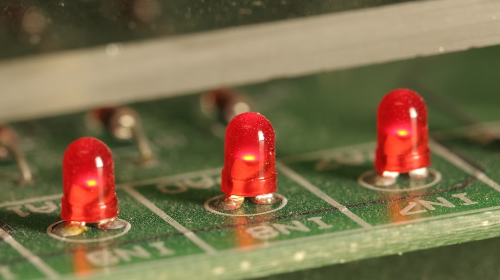
LED is short for a light-emitting diode, also known as a semiconductor diode. The LEDs are welded to a printed circuit board and fitted with a chip that generates light through an electrical connection. A heat sink and a ceramic base are used to attach the chips. There is no doubt that LED PCB is the core of LED lighting. An LED PCB is easy to generate a lot of heat, but it is difficult to cool with traditional methods. Metal core PCB is widely used in LED applications because of its strong heat dissipation ability, especially aluminum is often used in LED lamp PCB production. Typically, aluminum PCBS contains a thin layer of heat-conducting medium material that can transfer and dissipate heat much more efficiently than traditional rigid PCBS.
At present, patch packaging is the most widely used packaging form in LED applications. In general, a single LED component emits a limited amount of light. Therefore, a light fixture will use multiple LED components to get enough light. As with other semiconductor devices, PCBS is the best way to electrically connect LED components. PCBS with LED components is often referred to as "LED PCBS". As PCB technology continues to evolve, it paves the way for a number of exciting product innovations. A prime example is the development of PCBS for LED lighting. LEDs are welded to a circuit board and have a chip that produces light when electrically connected. A heat sink and a ceramic base are used to attach the chips.
An LED PCB board tends to generate a lot of heat, making it difficult to cool through traditional means. As a result, metal-core PCBS are often chosen for LED applications due to their enhanced heat dissipation. Aluminum is commonly used to make circuit boards for LED lights. Aluminum PCBS usually includes a thin layer of heat-conducting medium material that can transfer and dissipate heat much more efficiently than traditional rigid PCBS.
LED PCBS leads to applications
PCB LED lights can be incorporated into many lighting applications due to their combination of superior energy efficiency, low cost, and maximum design flexibility. Examples include automotive headlights, airport runway landing lights, lighting for military field applications, street lighting, highway tunnel lighting, photovoltaic (solar) lighting, flashlights and lanterns, traffic and signal lighting, hospital operating room lighting, high-growth plant lighting, and many others. In this case, it is essential that the buyer have accurate measurements of the various optical parameters of the lead.

LED parameter test
Leds must be tested during production and in their final application in order to achieve uniform output throughout their service life. Comprehensive optical characteristics are also essential in the research and development process of led and related products. This helps ensure that safety and performance standards are met. The easiest device for testing LEDs is a multimeter. If the multimeter shows its diode setting voltage of about 1600mV on the lead connecting the cathode and anode of the LED, it indicates that the LED is of good quality.
Parameters to be measured when testing leads
Some basic parameters, such as luminous flux, luminous intensity, spectrum, color, and spatial radiation pattern of LED, need to be measured during LED testing. Measuring different parameters helps to measure and define different characteristics, as shown below.
Color Rendering Index (CRI): The higher the color rendering index, the more accurate the color rendering. This is a way of measuring the ability of a light source to reveal the colors of various objects, compared to a natural light source, on a scale of 0 to 100.
Color temperature: The "warm" color temperature is usually 3000K or lower, while the "cold" color temperature is 4000K or higher.
Light intensity: This is the total amount of visible light emitted by a source, in lumens.
Power consumption: This is the rate at which energy is produced or consumed, in watts.
The Energy Star rating requires LED lights of 5 watts or higher with a minimum power factor of 0.7.
In order to test the life of the LED hardware, certain tests need to be performed. These tests include fatigue tests, assembly checks, dielectric pressure tests, functional tests, durability tests, and electromagnetic compatibility (EMC) tests. Fatigue testing helps to assess the durability of functional components over time. Assembly inspections help verify that the customer can easily assemble, install, and use the product. Dielectric voltage test measures current leakage and detects electrical breakdown or dielectric breakdown. According to the user manual, functional testing helps verify that the LED lighting product is working properly. Endurance tests, or run tests, evaluate the safety and functional performance of lighting products over time. EMC testing helps to ensure that LED lights do not emit excessive electromagnetic interference (EMI) during use. High EMI can damage or destroy other electronics in the same environment.

SMD LED in PCB
There are many devices that use surface-mounted components on PCBS, including LEDs. If the wire is thin, the through-hole assembly can be bent slightly so that it looks cheap from the outside. If the SMD LED is welded correctly, it will be rigid on the board. What's more, it can also put SMD LEDs behind the screen, while cheaper LEDs that use light bulbs will stick out through the packaging. So it can put the SMD LED on the small screen behind the packaging for your device to be cleaner. As you know, many PCBS that contain LEDs are made with multiple layers of FR-4 substrate, so you need a closely spaced pattern of filled or plated through-holes under each component so that it can transmit heat, as well as reach the power supply and ground layer.
If your Led has a small footprint and is surface mounted, you can use our through hole. There may be a weak solder spot or even a tombstone because it is not filled or the board is in the through the hole and then the solder will wick into the through hole during the assembly process so the reason why it is better to use SMD LED on LED lighting arrays is the problem with the wick. A single LED with decent power output will not cause damage to your circuit board due to inappropriate heat. However, if you are going to have a system for lighting applications, it will need to withstand a lot of heat from the plate that supports the led and make it difficult to cool the plate with traditional methods. Because a single led is too small, you can't fit a radiator anywhere, and the radiator will block the emitted light anyway. Because of the high demand for heat, metal core panels are commonly used in LED lighting applications because of their ability to dissipate large amounts of heat. Generally, aluminum is used as the metal core of PCBS for LED lighting applications. In addition, of all possible metal-core PCBS, aluminum is the most used metal. In addition, copper and iron are also used in metal core PCBS.

